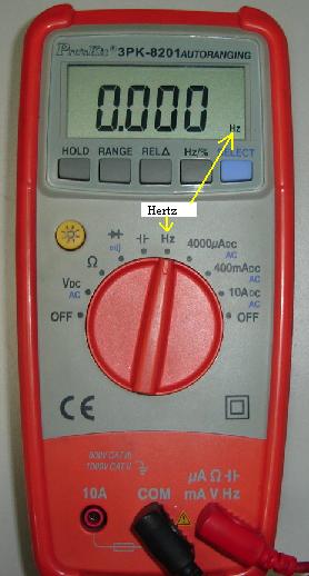
While supply is on you can check voltage at crystal pins is it varyng or not.
How to test ceramic resonator using multimeter.
I m off to college in the fall for ee so i will be on these forums more and more to ask questions and get help with homework anyway my question is i will hopefully have an oscilloscope soon and the first thing i want to use it for is to test the waveforms of ceramic resonators vs.
You cannot just take out your trusty meter and test the crystal in it.
Using an oscilloscope a crystal oscillator produces a sine wave when excited.
Begingroup if you have multi meter check continuity of crystal pad wrt respective ic pin.
A multimeter is an essential tool in any electronics lab.
Also is there any way of finding out what voltage or current i should or can use.
You ve learned how to measure voltage current and resistance and how to check continuity.
In this beginner s guide we ve shown you how to use a multimeter.
The impedance and phase characteristics measured between the terminals are shown in figure below.
To test the continuity of a wire you just need to connect each probe to the wire tips.
In fact there are three methods to test a crystal.
I have 2 quartz crystal resonators in my pcb board.
I want to test if these crystals are working properly or not.
It is appropriate then to see a waveform representative of a sine wave on the clock pins.
Testing the crystal is not a breeze either.
Endgroup electroholic dec 29 15 at 4 30 begingroup yes its also a way to test.
I m relatively new to these forums but i ve been watching eevblog for a long time.
But i am using a pic32 and it has very small pins.
They are connected to a freescale mc12311 transceiver ic which has an hcs08 micro controller embedded in it.
The ceramic resonator use the mechanical resonance of piezoelectric ceramics generally lead zirconium titanate.
Oscilloscope frequency meter digital counter digital multimeter.

